Inspection
|
It is a procedure to compare two different shapes and to measure their differences. |

|
Inspection is a procedure to compare two different shapes and to measure their differences. It is normally used to compare two models of the same objects surveyed at different moments in time. For example, it is used for monitoring barrels of nuclear waste to immediately detect possible deformations. The procedure Inspection is accessible from Outputs → Inspection of the top menu bar, from the corresponding button in the top toolbar, or from the contextual menu of any point cloud (structured or not) and any mesh. The result of the inspection is a new color layer that will be assigned to the point cloud. This color layer carries, for each point its measured distance from the reference model. After performing Inspection It is possible to use the Colors mapping dialog function to map these measures with colors chosen by user and to see the corresponding color scale and Histogram. |
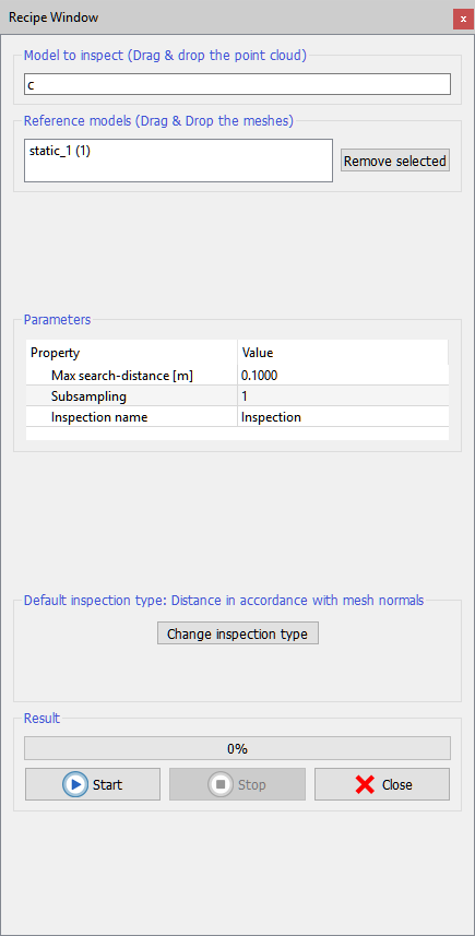
Input models
As inputs, user must provide a model to inspect and a reference model. The model to inspect must be a point cloud. The reference model must be one triangle mesh.
User can input the desired models by simply dragging and dropping them, or by pressing Load model to inspect and Load reference model. Press Remove to deselect undesired models from your import.
Parameters
At the center of the dialog there is the Parameters box that takes:
- Max search distance: every point of the model to inspect will be compared with the reference model only inside a sphere with a radius defined by this parameter.
- Subsampling (factor s): allows to balance speed versus precision.
There are two cases:
- Inspect an unstructured point cloud: the cloud will be divided in s sets of points and only one point in each set will be inspected. The other s – 1 points will be assigned the same distance value measured for that point.
- Inspect a grid point cloud: the procedure will scan the points according to their structure. The grid's structure will be divided in cells of dimension s by s. Only one point per cell will be inspected and the other points will get the same inspection value measured for the first.
- Inspection name: to define a name for the layer that will be that will be generated
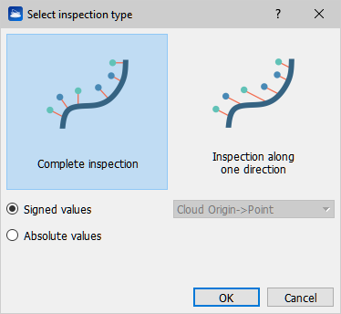
Inspection types
User can select the Inspection type to be performed by clicking " Change Inspection type" button.
|
There are three choices:
|
Finally, press Process to start the inspection. The resulting layer is appended to the color type list of the inspected point cloud, with the desired Inspection name. Use Colors mapping to optimize the display with a legend.
See this videotutorial to learn how to use the change detection tool.