Orthophoto viewer
|
To open a viewer to visualize and dimension 2D maps created in Reconstructor (both blueprints and x-ray orthophotos and standard orthophotos). |

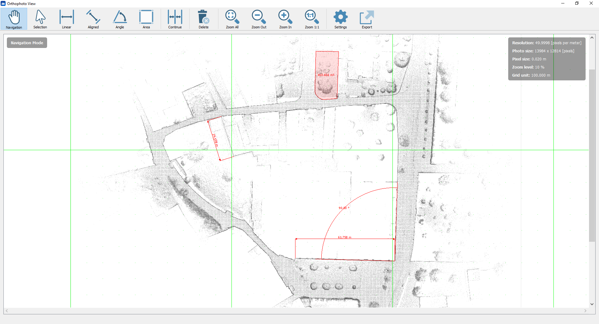
All the functionalities are below explained.
Navigation Mode
|
Navigation [Alt+1] Pan the view by clicking the left mouse button and releasing it when the desired view is achieved. |

|
Zoom out To decrease the blueprint zoom level. |
|
Zoom in To increase the blueprint zoom level. |
|
Zoom to Fit To zoom to fit the entire blueprint. |
|
Zoom 1:1 To zoom to the blueprint pixel size. |


|
Selection [Alt+2] Click on a item (e.g. a dimension) to add it to a multiple selection. Click on it once again to unselect it. Click a point to start a selection rectangle, drag out a box then click to another point to complete the selection. A different selection is due to a different direction by creating the rectangle:
Press Esc to cancel the rectangle Double click or press Esc to deselect all items. Press Del (Canc) or the command Delete to delete the selection. |

Measure Mode
|
Linear [Alt+3] To add a linear dimension, X or Y aligned. Click to pick the measure starting point. Move the cursor to seek the desired position of the dimension and then click when you found it. Hold the Alt key to axis-align the measure during the point selection. |
|
Aligned [Alt+4] To add a linear dimension, aligned to the distance between the ending points. Click to pick the measure starting point and then click to the end point. Move the cursor to seek the desired position of the dimension and then click when you found it. Hold the Alt key to axis-align the measure. |
|
Angle [Alt+5] To add a measure angle First click to pick the vertex of the angle measure, then click to pick the first side (a half-line will appear) and finally click to pick the second side. Move the cursor to seek the desired position of the dimension and then click when you found it. |
|
Area [Alt+6] To define a perimeter on the map and compute the area inside it. Click to pick the first vertex. Click to add polygon vertices until you complete your perimeter and then click the first vertex again to close the area (that will be colored in red). Move the cursor to seek the desired position of area's value annotation and then click when you found it. During the picking point press Esc to delete the latest point. |
|
Continue [Alt+9] If pressed after the Linear/Aligned/Angle commands, permits to add other dimensions, aligned to the latest one. |


After inserting the dimensions, they will be also listed in the Project Window as items related to the orthophoto.
|
Delete To delete the selection of objects made by the Selection tool. |

Settings
|
Settings [Ctrl+,] To set the viewer settings and the properties of the 2D image. |

Viewer Settings
Check/uncheck Show tools instructions to show/hide the suggestions about the commands use.
Check/uncheck Draw grid to show/hide the grid. Here you can also choose the grid colorization.
Note that the grid unit is depending on the zoom level.
By clicking on the Change units... button it's possible to change the current units of measure. Few preset are available, but different units of measure for lengths, areas and angles can be set, as well as the number of decimal digits.
Orthophoto (X-Ray) properties
Here the background (and foreground if you are managing a X-ray orthophoto) colors can be changed.
Also the color, the arrow size and the text size of the dimensions can be changed as you please.
The image resolution is displayed, as well as the total photo (image) size in pixels.
If the resolution is here changed, it's necessary to recreate (snap again) the orthophoto in order to save the changes.
Export
|
Export To export the orthophoto (including all the customized dimensions) in different formats: |

1. Image file
A *.png file is exported, keeping the same dimension and resolution of the original orthophoto.
2. AutoCAD Script
Several options are available to export your orthophoto to AutoCAD, in the settings dialog.
Export 3D position and orientation of orthophoto to AutoCAD: to choose whether you want to export to AutoCAD the plain 2D image, or whether also the 3D position and orientation that the image has in Reconstructor®'s current UCS should be exported to AutoCAD. Exporting the image's 3D pose to AutoCAD is useful if other items (e.g. polylines) related to the same model are exported to AutoCAD.
If you selected to export the 3D position and orientation as well, then the second checkbox is enabled.
Create new UCS in AutoCAD with same position and orientation of orthophoto: to choose whether you also want to create in AutoCAD a new UCS with the same position and orientation of the image, or not. If you selected to export the 3D position and orientation as well, then this checkbox is enabled.
Create new layer in AutoCAD containing the orthophoto: to choose whether to export the orthophoto in a new AutoCAD layer or in the current layer. Depending on the number of layers in the AutoCAD project, you may want to add a new layer or not.
Export dimension style: to give choice about whether to export also the dimension style (AutoCAD compatible) or not.
Please, note that the dimensions are saved in a separated layer in AutoCAD.
Click on Export button to automatically save an image (*.png format) within together a script file (.scr).
|
Suggested steps for orthophoto export to AutoCAD Click on Save Orthophoto button: an image (.png) and a script file (.scr) will be created. Create and Save a .dwg file in the same folder of the exported orthophoto (acadISO format suggested) Drag&Drop the script file in AutoCAD .dwg file just created: the orthophoto will be automatically positioned in the 3D space if you flagged Export 3D position and orientation of orthophoto to AutoCAD in Export to AutoCAD settings, otherwise you need to define the origin of the orthophoto in the XY plane of the current UCS. If you need to reset the orthophoto, you have to "Detach" it, save the AutoCAD project and drag&drop the script file another time. |
To export and save the orthophoto and the relative dimensions in a *.rec2dv format, readable from the free Gexcel 2D viewer GoBlueprint.
By opening it in GoBlueprint, all the properties of the orthophoto and its dimensions are kept.
Note
If changes are applied from the last time you open the orthophoto viewer, you are asked to redo the snap.
![]() The Logarithmic Transform is suggested as contrast enhancement algorithm: the greater is the point cloud density in the view direction, the greater is the contrast (according to a logarithmic function).
The Logarithmic Transform is suggested as contrast enhancement algorithm: the greater is the point cloud density in the view direction, the greater is the contrast (according to a logarithmic function).