Mesh Editor
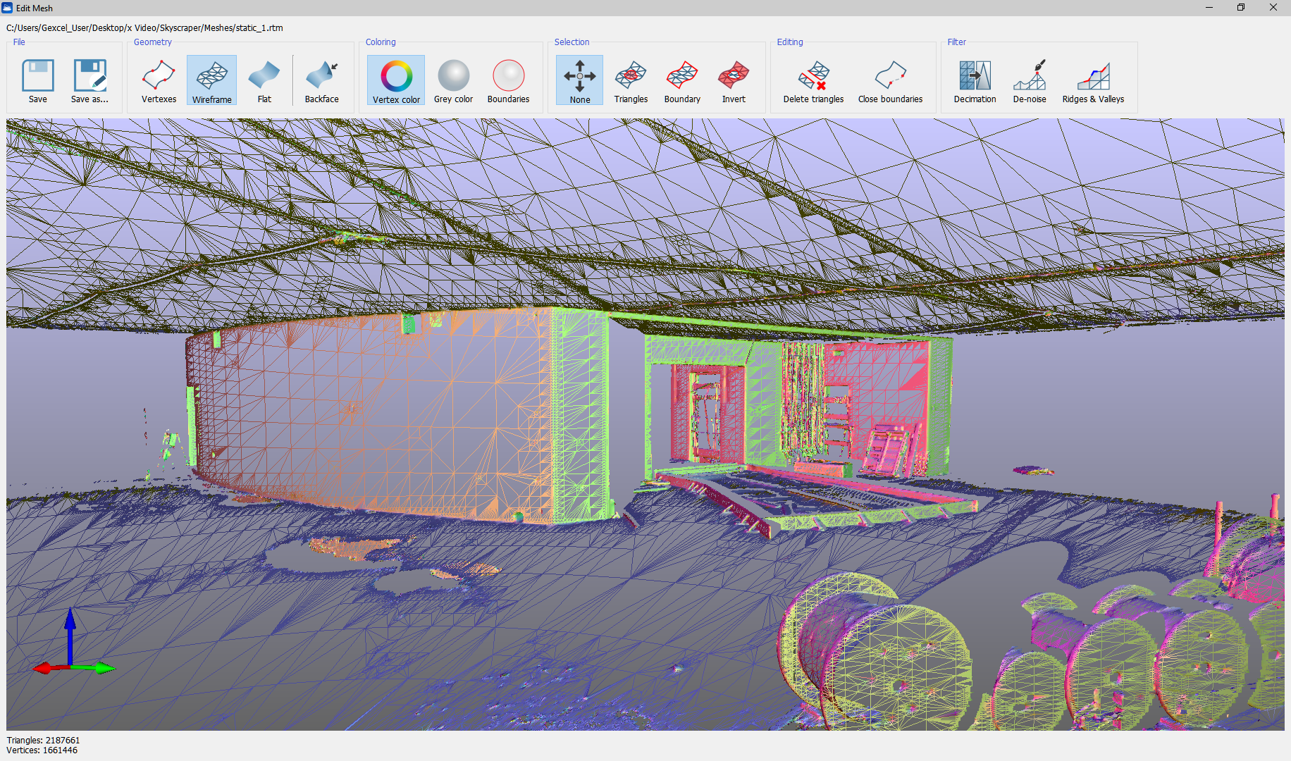
This dialog is an environment designed for advanced mesh editing operations. It works on one mesh at a time. It is accessible from Tools->Meshing->Mesh editor, from the corresponding button in the top toolbar, or from the context menu of any mesh in the project window.
From top to bottom, the dialog displays the mesh's full path, then a toolbar with groups of buttons, then a navigable 3D view to show the mesh, and lastly information on triangles and vertices count.
Top toolbar
File
This button group provides the Save and Save as options. These are needed because the edits performed in this dialog are not automatically transferred to the mesh in Reconstructor®'s project. In fact, if you close the dialog you are asked if you want to save or discard the changes.
Geometry
This button group allows you to switch between the three visualization possibilities of a mesh: only vertices, only triangle edges (wireframe), or the triangle's faces (flat). The button backface allows you to show or hide the triangles' backface.
Coloring
The first two buttons here allow you to change how to color the mesh: using the colors associated to the vertices, or using a gray color that changes only according to the triangles' inclination with respect to the light source. The button boundaries highlights in bright red all the boundary edges of the mesh, and it is particularly useful to quickly spot where the mesh has holes to fill or imperfect boundaries that should be corrected.
Selection
Here you can use several selection modes.
When the button None is checked, you can navigate the mesh. By clicking Triangles, you start selecting the mesh triangles by drawing a rectangle on the viewport. Selected triangles are highlighted in yellow. The button Invert enables you to invert the current triangles selection. When you are drawing the selection rectangle, keeping pressed Shift will enable you to add triangles to the current selection by drawing another selection rectangle. The button Boundary turns on another selection mode. In this mode you can select one of the circular boundaries that the mesh has. Boundaries are polygons formed by those mesh edges who belong to one and only one triangle. A closed mesh has no boundaries. Boundaries selected in this mode may delimit a hole that you want to close. After selecting the hole's boundaries, you can click on Close boundaries in the Editing button group.
Editing
Once you have selected some triangles with the button Triangles explained in the former paragraph, you can delete the selected triangles with Delete triangles. The button Close boundaries allows you to close a mesh hole whose boundaries have been selected. This function works best with small and with close-to-planar holes.
Filter
This button group contains three functions:
|
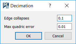
This tool allows you to simplify your mesh substituting small triangles with bigger ones if the mean-square error introduced in this way is smaller than a user-customizable threshold.. Simplification is based on conveniently collapsing edges among triangles. For each edge shared by two triangles, Reconstructor® assesses whether collapsing it or not. Collapsing an edge means assigning the edge's two vertices to coincide in the edge's middle point, and adjusting all neighboring triangles consequently. If the quadratic error between the surface before and the surface after the collapsing is below the parameter Max quadric error of the dialog, then the edge is collapsed. The algorithm tries to collapse a percentage of edges as specified by the parameter Edge collapses, where 0.1 stands for 10%. |
|
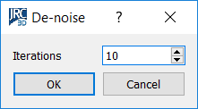
This algorithm allows you to de-noise your mesh, meaning to iteratively eliminate spikes from your mesh, without changing the surface's volume. A smoothing filter is run on the mesh for as many times as the parameter Iterations says. This filter has anisotropic properties: it eliminates the spikes without changing the surface's volume. Along the iterations, it distributes the volume from the spike to the neighboring triangles. |
|
|
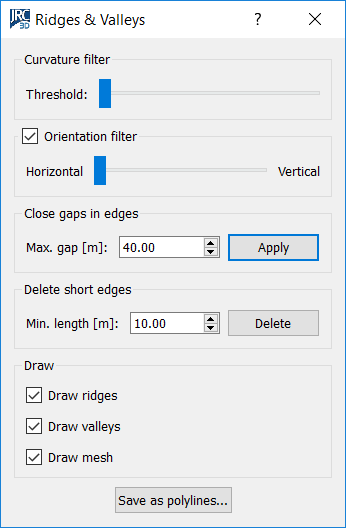
This is a semi-automatic technique to detect Ridges (prominent mesh edges) and Valleys (reentrant mesh edges). When you open this dialog, the ridges and valleys are calculated and drawn in the mesh editor. Ridges are drawn as blue polylines, valleys are in red. Ridges and valleys can be then saved as polylines. The idea is that tool shows you an initial extraction of ridges and valleys, successively you refine the parameters of extraction and see the effects of your changes in real time. You can refine the parameters until you are not satisfied, and then save the ridges and valleys as polylines in the project. The parameters of ridges&valleys extraction you can modify regard the curvature, the horizontality, the length of the edges and the gaps between them. While you modify the parameters and recompute the ridges&valleys, you can choose to turn on or off the visualization of the ridges, the valleys and the mesh, via the three check-boxes in the Draw groupbox at the bottom of the dialog. Curvature filter The topmost slider of the dialog allows you to modify a threshold on the curvature of the ridges and valleys. Ridges and valleys are edges shared by your mesh's triangles. Each edge has a curvature associated, depending on the angle between the two associated triangles. A threshold on the curvature filters out the smoother edges and leaves only the steeper ones, which normally are the most important. Scroll the slider to see the effect of the threshold in real time. Orientation filter Below the curvature filter, you can also activate a orientation filter. This filter keeps only the edges whose angle with respect to the horizontal plane is close to the angle you indicate with the slider. In this way, you can choose to keep only the horizontal edges, or the vertical ones, or the ones with a given inclination. Close gaps in edges Sometimes ridges and valleys come in many segments with small gaps among them. In the groupbox Close gaps in edges you find a tool to close those gaps and get the ridges and valleys as continuous polylines. You can set the maximum gap distance to close, and press Apply. Reconstructor will start closing the gaps from the smallest to the biggest, without creating loops or bifurcations. Delete short edges In the Delete short edges a tool comes to filter out polylines whose total length is less that the specified parameter. Normally you want to discard short edges because they are not the main ones. The main ones should instead be found by closing the gaps among them. General procedure As general procedure, we advice to use the described filters in the order given above, and to close and open the dialog if the result is not satisfactory. Once the extracted ridges and valleys are good enough to describe the important edges of your model, press Save as polylines at the bottom of the dialog. New polylines with the ridges and valleys will be added to your project. |