Flythrough (video trajectory)
|
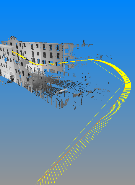
A flythrough, or video trajectory, is a trajectory that runs in your 3D scene, defining how a video camera will move around in your scene to capture a movie. A flythrough is the “backbone” of the movie you're creating of your 3D scene. In the picture above, the red curve line is the trajectory that the video camera does. The yellow segments are the optical axes of the video camera for each video frame. |
Flythrough creation
The easiest way to create a flythrough is by using the flythrough editor: you can define keys, or important positions you want your video to pass through, and then interpolate the remaining frames. You can also create a flythrough from point list. The difference is that with the point list window you can only use points that belong to existing models to define your trajectory, meanwhile with the flythrough editor you can choose your keys freely.
Operations on flythroughs
If you right-click on any flythrough, you have access to some useful operations. You can play the flythrough, to see a preview of the video associated with it. You can edit the flythrough, and then the flythrough editor will appear to allow you to add or delete keys to your trajectory. You can make movie, and then the movie dialog will enable you to specify the video encoding parameters to produce the final video.
- Cylinder virtual scan. This function will enable you to virtually scan your 3D scene by looking at it from a cylindrical camera whose “backbone” is the flythrough. More concretely, Reconstructor® will split your trajectory in many segments, each segment running from point T(t) to point T(t + 1), where T(t) indicates the point on trajectory T at time t. Out of each one of those segments, a cylindrical camera will be created having as main axis the segment. Reconstructor® will pop up as many virtual scan dialogs as the segments are, to allow you to do a virtual scan.
- Generate cross sections. This function provides you with a way to create cross sections of your models along the trajectory. If you select this function, Reconstructor® asks you the spacing between different cross sections along the trajectory. When the spacing is set, Reconstructor® creates several planes, with the normal placed along the trajectory and placed according to the spacing selected. These planes are added to the project and named Flythrough section n(N). It is left to you to actually select one of these planes and calculate the desired cross section.
You can also convert the flythroughs into polylines by using the Convert to polyline command in the contextual menu.