Virtual Scan
This function is called Virtual Scan because you can imagine it like a scanning of the loaded models in the 3D window with a virtual laser scanner (a virtual camera).
In addition you can set up the near view plane (from which to start viewing the objects) and the far one.
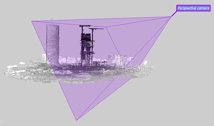
This function is used to resample the 3D dataset on a 2D grid from a defined position in 3D space and with a defined projection (orthogonal, perspective, cylindrical, spherical). Checks the models that must be scanned in the Project Items Window, and the depth range of the scan (near and far clip planes) of the current camera. Can create snapshots, cube maps or grid point clouds.
Parameters:
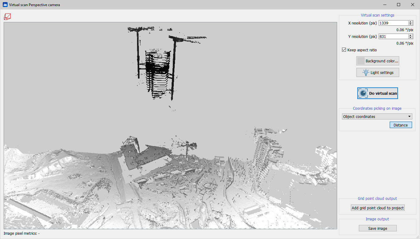
- Update preview: creates a preview of the scan from the selected view point and projection. Select the resolution and background color first.
Pick mode:
- Distance: press Left Mouse Button (LMB) for the first point and keep it pressed while dragging the mouse to the second point, then release the LMB. Both endpoints must be valid 3D points!
- Point: double click LMB to pick a list of 3D points from the virtual scan. If the AutoCAD link is enabled, the points are sent to AutoCAD. Check Global Coordinates for reading global/local coordinates.
Save cube map: (orthographic camera only) use this view point to construct a cube map of the scene, i.e. 6 square images (the faces of the cube) of size Width with perspective projection (90 degrees vertical field of view) are generated around the centre of projection and saved to file.
Save image: save the current virtual scanned image to file.
Save grid point cloud: create a grid point cloud from the current virtual scanned color and depth. The model is automatically added to the project.
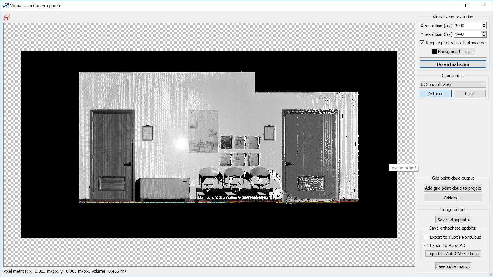
The bottom row of the dialog shows the unit scale (depends on the type of projection) of the image and the computed volume between the plane of projection and the visible 3D data. For best results use triangle meshes, so no holes are found on the surfaces. Otherwise, try to increase the point size of the cloud of points in the Property Editor.
Orthophotos
A virtual scan of a plane/ortho camera or projector will be an orthogonal projection and thus an orthophoto. If the image is saved with Save image, a text file is created along with the image file which exports registration information of the ortho image in the scene.
Simultaneously with saving the image a script for AutoCAD® is generated. It allows, by simply drag&dropping in the AutoCAD® window, to load the orthophotos in the correct position and scale, (in a blue layer with the same name dedicated to image). It also creates a UCS having XY drawing plane coincident with the image plane and positioned in the lower left side of the orthophoto, in order to facilitate the user in redrawing of vectorial draw.
Press the Export to AutoCAD settings button to choose the options.
Remember that the DWG file (template acadiso) must be saved in the same folder and the script files (* .scr).
Gridding: this process computes the optimal estimation for missing points in a grid of size MxN, given K valid initial points. The algorithms available are: simple kriging (user has to specify the global mean), ordinary kriging (the mean is computed automatically), kriging with trend (the mean varies smoothly). Gridding is a demanding process, the time complexity is O(K²MN), so use as few as possible initial points.
Export 3D position and orientation of orthophoto to AutoCAD: to choose whether you want to export to AutoCAD the plain 2D image, or whether also the 3D position and orientation that the image has in Reconstructor®'s current UCS should be exported to AutoCAD.
Create new layer in AutoCAD containing the orthophoto: to choose whether to export the orthophoto in a new AutoCAD layer or in the current layer. Depending on the number of layers in the AutoCAD project, you may want to add a new layer or not.
Create new UCS in AutoCAD with same position and orientation of orthophoto: to choose whether you also want to create in AutoCAD a new UCS with the same position and orientation of the image, or not. If you selected to export the 3D position and orientation as well, then this checkbox is enabled.
Suggested steps for orthophoto export to AutoCAD
- Click on Save Orthophoto button: an image (.png suggested) and a script file (.scr) will be created.
- Create and Save a .dwg file in the same folder of the exported orthophoto (acadISO format suggested)
- Drag&Drop the script file in AutoCAD dwg file just created: the orthophoto will be automatically positioned in the 3D space if you flagged Export 3D position... in Export to AutoCAD settings, otherwide you need to define the origin of the orthophoto in the XY plane of the current UCS.
- If you need to reset the orthophoto, you have to "Detach" it, save the AutoCAD project and drag&drop the script file another time.
See also Create Orthophoto.