Cross section
|
|
To create a cross section of your models you can access the relative command in the top toolbar or from the planes' context menu. |

You can make cross sections of grid point clouds and meshes. However, it is not possible to make cross sections of unstructured point clouds.
Cross sections are defined with respect to a plane.
With the default settings, the section is defined as a polyline created by cutting all loaded models with the plane. However, it is also possible to have multiple cross sections by defining more slices or additional cutting planes, all parallel to the original plane and lying at a certain distance from it.
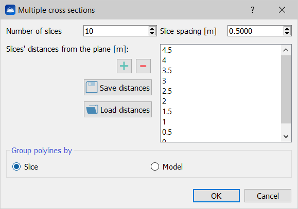
In the top left spinbox you can specify how many slices you want, the default is one. The top right spinbox allows you to specify the default inter-slice distance. By editing these two parameters, you will notice that the values in the panel on the right in the dialog are changing. These are the list of the slices' distances from the plane. By double-clicking on a single distance, it is possible to edit individually each distance. Furthermore, it is possible to add (green “plus” button) and remove (red “minus” button) the currently selected slice. There are also two buttons to Save the distances and Load the distances: these are useful when you have to use the same distances set for many cross sections.
Distances are defined on the plane's Z axis, therefore 0 means “slice lying on the plane”, and the positive direction is given by the direction of the plane's Z axis. You can invert the plane's direction with the appropriate command in the plane's context menu. It is also possible to have negative distances, by double-clicking on them and writing a negative number.
Towards the bottom of the dialog there is the Group polylines by panel, with the option to either group the output cross sections by Slice or by Model. With the first option, one cross section will be created for each slice, regardless of how many models the slice crossed. With the second option, only one cross section will be created for each model crossed, regardless of how many slices crossed that model and where.
![]() It is possible to use this last modality to create isolines (contour lines).
It is possible to use this last modality to create isolines (contour lines).
When you press Ok, the specified cross sections are computed and added to the project under the Cross sections items group. Cross sections can be exported in DXF for AutoCAD.