Cross Sections
This submenu contains commands and features to create cross sections and isolines of point clouds (grid or unstructured) and meshes, starting from cutting planes and other constraints:
- Create/edit plane
- Cross sections
- Contours
- Quick profile
- Cross sections from planes
- Section from plane
- Tunnel cross sections
![]() Note that only 3D models (point clouds or meshes) loaded and displayed in the 3D window will be considered in the sectioning processes.
Note that only 3D models (point clouds or meshes) loaded and displayed in the 3D window will be considered in the sectioning processes.
Advanced cross sections structure overview
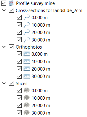
Section from plane, Contours, Quick profile and Tunnel cross sections tools give as output a special Survey item composed by one orthophoto, one cross section polyline and one slice of point cloud (![]() if required and if sectioning point clouds) for each extracted section.
if required and if sectioning point clouds) for each extracted section.
|
|
These items are merged in groups named
Note that when sectioning more than one 3D model, one group per each model will be created including the polylines sections concerning that model. Only one group will be indeed created both for Orthophotos and Slices items. In particular, to create any single Slices item a merging of different point cloud portions is done. |
Several features are common in Section from plane, Contours, Quick profile and Tunnel cross sections tools. They are explained below.
Navigation across sections
During cross section display a preview of the final cross sections, any navigation modalities are available in the recipe window.
|
|
Map view This navigation mode places the view so that all the selected items can be seen from a top view. |
|
|
Default view This navigation mode allows the user change the current view so that all the selected items are completely visible in the 3D scene. |
|
|
Section view This navigation mode automatically switches the view to orthographic mode and aligns it to the cross section view. |
|
|
Left and right arrows The arrows can used to switch from a cross section preview to another. |


Section Survey Settings
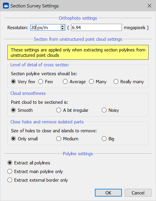
By clicking ![]() button the settings parameters can be changed to manage the orthophotos' resolution and quality of extracted polylines.
button the settings parameters can be changed to manage the orthophotos' resolution and quality of extracted polylines.
|
|
Orthophoto settings The resolution is automatically computed according to orthophoto's dimensions, but it is possible to manually change it. The resulting dimension ( in megapixels) will be computed and displayed. Section from unstructured point cloud settings When sectioning unstructured point clouds further settings can be used to extract more detailed cross sections polylines. Level of detail of cross section: you can specify how many vertices you want to use for your output polyline. The more the vertices, the finer the details that will be reconstructed. Cloud smoothness: if your cloud represents clean construction data, then select Smooth. If, however, your cloud contains noisy data, then select Noisy. Close holes and remove isolated parts: you can here specify the size of the holes that are going to be closed in the polyline, and the size of the “islands”, small disconnected components that may have been created. The size is computed as ratio between the length of the hole/island and the length of the whole polyline. Polyline settings The cross sections polylines are computed interpolating the slice of point cloud at the turn of the cutting planes. By selecting one of the following options you can define the degree of extraction of cross sections polylines to be included into the final section survey. These settings must be mainly managed in tunnels sectioning. Extract all polylines: to keep all the edges obtained from the intersection between cutting plane and model's slices. Extract main polylines only: to delete short edges from polyline. Extract external border only: to close holes in main borders, keeping only most external borders. Be careful when more tunnels or hollows are intersecting in the same section. |
|
|
Compute After managing cutting planes and parameters click on Compute to extract the sectioning outputs. After creating a Section Survey, it will appear in the Project Window items list. |

You can access the results at any time by the Survey's context menu, clicking on View cross sections command: the Orthophoto viewer also displaying polylines and slices will be opened.
Export Section Survey
All the created items can be exported individually through the traditional export commands.
In the Survey's context menu another possibility is available: through the Export section survey command you can export all the objects in a single step.
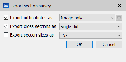
To do it, flag and define the exportation options, according to your purposes.
|
|
Export orthophotos as Image only: to export only an image file, not scaled and not georeferenced Image + AutoCAD script: to export an image file within a script file to import scaled and georeferenced images in AutoCAD (see also Exporting orthophotos to AutoCAD) Export cross sections as Single dxf: to export cross sections as polylines where any group of polylines will be included in a single .dxf file Multiple dxf: to export all the cross sections as polylines in a single .dxf file Multiple Shape files: to export all the cross sections in a single .shp file Export section slices as E57/LAS: to export the slices as point clouds in E57 or LAS format. |