Create/edit plane
|
|
This is a toolbox for creating/editing a plane from points, axes, objects, UCS directions, etc. Start by dragging and dropping in the editor window the plane you want to edit. If no plane is dropped, a new plane will be created when you activate any of the functions or when you click on |
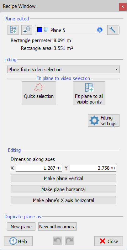
Fitting
Several criteria are defined to fit the plane.
Creating a plane from two points
This option allows you to create a vertical plane from - or to make your plane pass by - two points. To define one of these points, just click on  and double click on any point in the 3D scene. Otherwise, select any point from the point list window by clicking on ... . It is also possible manually insert the coordinates of the points in the dedicated boxes. When you have defined the points, click on Fit plane. The plane will be adjusted to pass by the specified points, to be vertical (coplanar to the Z axis of the current UCS) leaving as much as possible unchanged the other plane's properties.
Creating a plane from video selection
This option allows you to create a plane from a video selection of point clouds.
Click on Quick selection to use the Lasso tool to make a free hand selection in the point cloud view. Automatically the plane will be created, fitting the selected points.
Click the Fit plane to all visible points button to create a plane fitting all the points visible on the 3D view (in the foreground).
Creating a plane from point list
This option allows you to create (or adapt) a plane from the point listed in the project.
Creating a plane from segment and point
This option allows you to create a plane from a segment and a point included in the project.
Select the segment and the point in the Project Window then drag&drop them in the provided boxes.
Two modalities are available to fit the plane:
- The chosen segment is the normal plane: the plane will be perpendicular to the segment
- The chosen segment must lie on the plane: the plane will have the segment lying on it and will pass by the point
After choosing the modality and the segment/point entities, click the Make plane from segment and point button to create/modify the plane.
Creating a plane from origin and axes
This option allows you to create a plane from - or to make your plane pass by - three points. These points are the center of the plane (UCS origin), the X (or Y) axis endpoint, and a point on XY plane. To define one of these points, just click on and double click on any point in the 3D scene. Otherwise, select any point from the point list window by clicking on ... . It is also possible manually insert the coordinates of the points in the dedicated boxes. When you have defined the point(s), click on Fit plane. The plane will be adjusted to pass by the specified points, leaving as much as possible unchanged the other plane's properties.
Creating a plane from bounding box
This option allows you to create a plane from the faces of the cumulative bounding box of the currently selected project items. This is useful for example to immediately create the base plane of a certain church or cave, to make plants or sections later.
When you create/edit a plane from the bounding box of project item(s) (bottom group box), the plane's direction is determined by the current UCS: frontal, lateral and base plane mean that the plane's normal is parallel to the UCS' X, Y and Z axis respectively.
For some modalities, a default set of fitting parameters can be adopted or modified to interpolate the points.
Among the selected points, the RANSAC algorithm randomly selects X points and tries to fit the geometric shape on them.
The algorithm then iterates this procedure N times keeping the best result that it found among all attempts. The quality of the fitting is given by how many points (out of the selected ones) are sufficiently close - and therefore belonging - to the geometric shape (inliers).
The maximum value of X is given by the Maximum points used for fitting [#] parameter.
The RANSAC minimum iterations [#] parameter defines the minimum number of attempts N that the algorithm must make before considering the geometric shape correctly fitted.
Inliers maximum distance [m] defines the maximum distance within which a point is considered to belong to the geometric shape.
Editing
Once the plane is defined, it can be edited by setting the dimensions along X and Y axes.
It can be also oriented according to the vertical horizontal directions (respectively parallel to Z axis and XY plane), as well as its X axis can be forced to be horizontal.
Duplicate plane as
The selected plane can be duplicated as a
- New plane: a new and identical plane will be added to the project
- New Orthocamera: a new orthocamera in which the projecting plane will be the same plane will be added to the project.
![]() This option is useful when you want to extract a cross section and an orthophoto (or X-ray orthophoto) from the same position: create the cutting plane to generate the cross section, duplicate it as an orthocamera and use it to generate an orthophoto from the same point of view.
This option is useful when you want to extract a cross section and an orthophoto (or X-ray orthophoto) from the same position: create the cutting plane to generate the cross section, duplicate it as an orthocamera and use it to generate an orthophoto from the same point of view.
|
|
The functions explained before are more powerful if used in combination. For example, first you create a plane from three points of a façade, then you make the plane vertical, or its X axis horizontal, to create later an orthocamera from it. Note also that, while you edit your plane, you have the undo/redo buttons on the bottom of the dialog, to make the editing process easier. When you are done, just close the window. If you want to start a new plane, click on I'm done, create a new plane. |