Multiresolution Meshing
Multiresolution Meshing is possible only with Grid point clouds. If you want to generate a mesh from an Unstructured point cloud, first transform it in a Grid point cloud by using the Virtual scan tool.
|
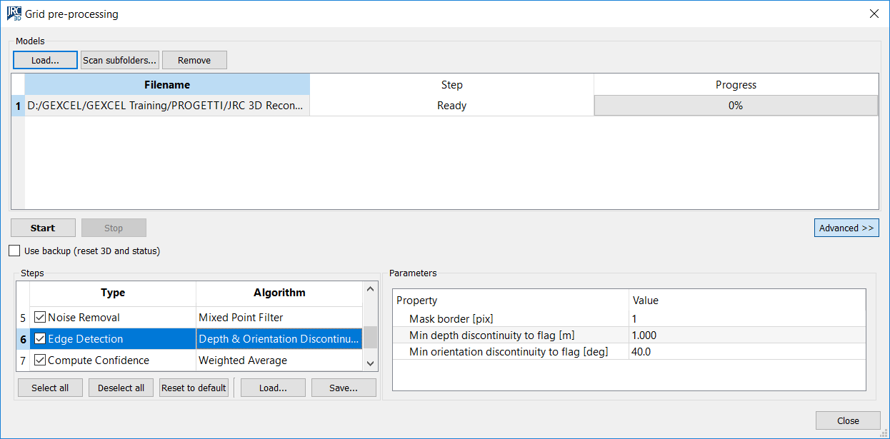
NOTE Before meshing you need to Preprocess the Grid. During the meshing the software will use the Edges calculated at the pre-processing stage:
|
|
|
|
|
|
The Multiresolution Mesh tool is accessible from Data management→Meshing→Multiresolution Mesh, from the corresponding button in the top toolbar, or from the context menu of grid items in the project window. |
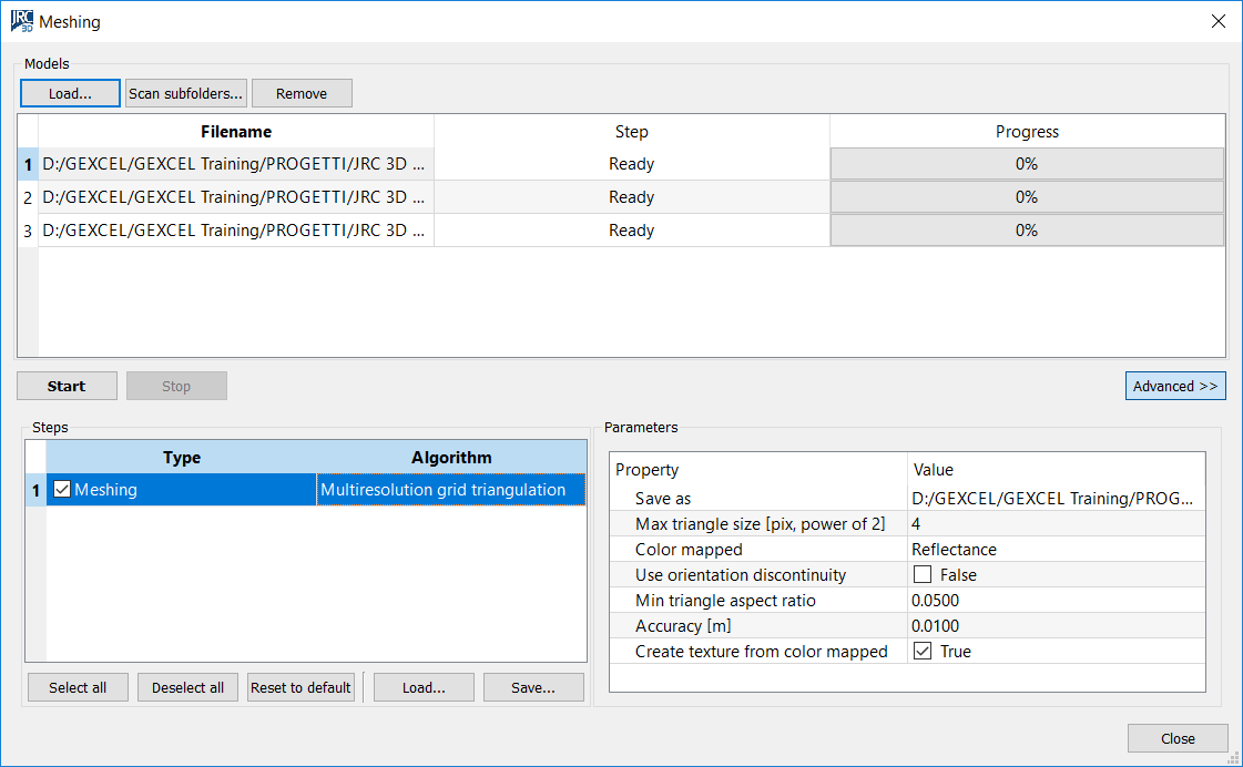
- Press Load to add an external grid point cloud or Scan subfolders to find automatically all grids in a folder and its subfolders. Press Remove to remove undesired grids.
It is possible to process grids present in the current project by selecting Meshing from the context menu of the grid item in the Project Window. In this case, when the processing is finished, the grid is unloaded from the project to free memory. Please force the reloading to refresh the rendering.
- Press Start to run the processing. This plug-in creates a separate thread for each grid so if multiple CPUs are available the processing is sped up proportionally.
The meshing process is applied consecutively to the selected grid by pressing the Select All button.
- To modify the meshing parameters press Advanced, then select one or more rows in the list of models with [Ctrl] or [Shift] keys. The parameters are updated for all the selected models.
- It is possible to Save the meshing parameter and Load them for other scans or projects or Reset them to default values.
Triangulation
The triangulation algorithm can be changed by clicking (three times) the algorithm name, so a combo box of available algorithm is shown.
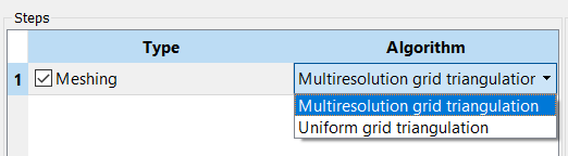
Uniform
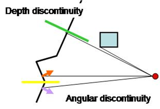
All the 3D valid points are connected with triangle meshes to build the range surface, without simplification.
The algorithm checks if 2 points are divided by a depth discontinuity, in that case no “false” triangles are created.
Save as: check the file name of the resulting mesh.
Color mapped: select the color assigned to the vertexes of the mesh (e.g. Reflectance, Color, Inclination, Confidence, …)
Multi-resolution
Simplified (lighter) triangle meshes are created in “flat” areas and dense triangle meshes are created in geometrical complex areas (close to edges or curvatures), satisfying an approximation error threshold.
Save as: check the file name of the resulting mesh.
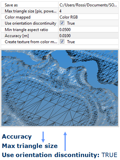
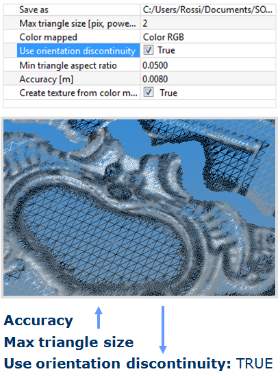
Max triangle size [pix power of 2]: 2 [number of points],, it’s the size of initial triangle; the value you can set is [number of points] you want to skip in the flat area. The higher the value, the more the mesh gets simplified. As example, a value of 4 means that a triangle will be created for a square wide 2^4=16 pixels. If the approximation error is too high, the triangle will be subdivide in smaller pieces.
Color mapped: select the color the color layer you want to map.
Use orientation discontinuity: thepre-processed orientation discontinuity is used to drive the subdivision process in order to preserve features such as edges. Set to TRUE to have more triangles around the edges.
Min triangle aspect ratio: minimum accepted triangle aspect ratio. If the triangle is too thin it will be subdivided in smaller pieces. This test is performed only for the initial triangle.
[Note: Aspect ratio of a triangle is the ratio of the inradius to its circumradius). The aspect ratio of a triangle lies between 0 and 0.5. For triangles with an angle near to zero, the aspect ratio is 0; for equilateral triangles, the aspect ratio is 0.5.]
Accuracy [m]: max approximation error of the mesh. The higher the value, the lesser triangles you have.
Create texture for color mapped: a texture is generated from the selected Color mapped on the mesh. Set to TRUE if you want the color layer not to lose resolution with the mesh simplification.
In the images below an example of the use of two different set of parameters is showed.
|
|
|
See also other Meshing techniques.