Orthophoto Viewer
|
|
To open a 2D viewer to visualize and dimension 2D blueprints created in Reconstructor. |

All the functionalities are below explained.
Navigation Mode
|
|
Navigation [Alt+1] Pan the view by clicking the left mouse button and releasing it when the desired view is achieved. |

|
|
Zoom out To decrease the blueprint zoom level. |
|
|
Zoom in To increase the blueprint zoom level. |
|
|
Zoom to Fit To zoom to fit the entire blueprint. |
|
|
Zoom 1:1 To zoom to the blueprint pixel size. |


|
|
Set the axes origin [Alt+LMB] To define a picked point as origin of the axes of the displayed grid. |
|
|
Reset the axes origin [Alt+RMB] To reset the origin of the axes of the displayed grid to the left bottom corner of the orthophoto. |
|
|
Selection [Alt+2] Click on a item (e.g. a dimension) to add it to a multiple selection. Click on it once again to unselect it. Click a point to start a selection rectangle, drag out a box then click to another point to complete the selection. A different selection is due to a different direction by creating the rectangle:
Press Esc to cancel the rectangle Double click or press Esc to deselect all items. Press Del (Canc) or the command Delete to delete the selection. |

Measure Mode
|
|
Linear [Alt+3] To add a linear dimension, X or Y aligned. Click to pick the measure starting point. Move the cursor to seek the desired position of the dimension and then click when you found it. Hold the Alt key to axis-align the measure during the point selection. |
|
|
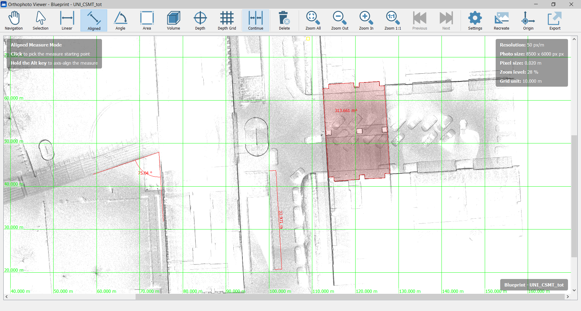
Aligned [Alt+4] To add a linear dimension, aligned to the distance between the ending points. Click to pick the measure starting point and then click to the end point. Move the cursor to seek the desired position of the dimension and then click when you found it. Hold the Alt key to axis-align the measure. |
|
|
Angle [Alt+5] To add a measure angle First click to pick the vertex of the angle measure, then click to pick the first side (a half-line will appear) and finally click to pick the second side. Move the cursor to seek the desired position of the dimension and then click when you found it. |
|
|
Area [Alt+6] To define a perimeter on the map and compute the area inside it. Click to pick the first vertex. Click to add polygon vertices until you complete your perimeter and then click the first vertex again to close the area (that will be colored in red). Move the cursor to seek the desired position of area's value annotation and then click when you found it. During the picking point press Esc to delete the latest point. |
|
|
Volume [Alt+7] Drawing a planar area on the blueprint with a guided polyline selection, the volume identified by projecting this area along a user-defined depth is computed. |
|
|
Depth If the Depth computation is performed during orthophoto creation, a labeled point is added to the blueprint's measures by clicking on a chosen pixel in the image. The label indicates the value of the depth (or altitude) referred to the pixel position. See also the Depth Grid in Orthophoto Viewer video tutorial. |
|
|
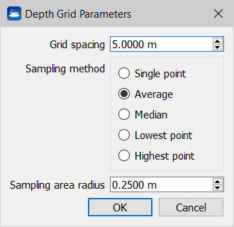
Depth Grid If the Depth computation is performed during orthophoto creation, a labeled grid is added to the orthophoto's measures: the Grid spacing, the Sampling method ("Which point you want to extract from the 2D image?" "The lowest in altitude to create a DTM", for example) and the Sampling area radius (the average value is computed within the circle defined by a range of influence around the node) are set in the Depth Grid Parameters dialog
while the position of the grid is defined by clicking on a chosen pixel in the image. The labels on the nodes of the grid indicate the values of the depth (or altitude) according to their position. See also the Depth Grid in Orthophoto Viewer video tutorial. |
|
|
Continue If pressed after the Linear/Aligned/Angle commands, permits to add other dimensions, aligned to the latest one. |


After inserting the dimensions, they will be also listed in the Project Window as items related to the blueprint.
|
|
Delete To delete the selection of objects made by the Selection tool. |

Settings
|
|
Settings To set the viewer settings and the properties of the 2D image. |

Viewer Settings
Check/uncheck Show tools instructions to show/hide the suggestions about the commands use.
Set the Draw grid to hide (None) or show the grid, that can be Adaptive (where the grid unit is depending on the zoom level), or at a Fixed step. You can also choose the grid colorization.
By clicking on the Change... button it's possible to change the current units of measure. Few preset are available, but different units of measure for lengths, areas and angles can be set, as well as the number of decimal digits.
Orthophoto (X-Ray) properties
Here the background (and foreground if you are managing a X-ray orthophoto) colors can be changed.
![]() To set a transparent background set the alpha channel to 0 (zero) in the Background color options.
To set a transparent background set the alpha channel to 0 (zero) in the Background color options.
Also the color (RGB and alpha channel), the arrow size and the text size of the dimensions can be changed as you please.
The image resolution is displayed, as well as the total photo (image) size in pixels.
If the resolution is here changed, it's necessary to recreate (snap again) the orthophoto in order to save the changes.
|
|
Recreate To regenerate the orthophoto with the currently visible point clouds. In case of X-Ray orthophotos, the system will ask you which clouds you want to include in the regeneration. |

|
|
Origin To set a new origin of the orthophoto by double left clicking on an orthophoto's pixel, setting the axes and depth origin. Double right click to reset axes and depth origin. Here you can only change the origin of the axes or change both the origin of the axes and the origin of the depth. The second option will invalidate any existing depth measures. |

Export
|
|
Export To export the blueprint (including all the customized dimensions) in different formats: |

1. Image file
The orthophoto, as it is displayed, is exported in a picture format [.bmp, .jpg, .jpeg, .png, .tif, .tiff] , keeping the same size [pixels] and resolution [pixels/unit of measure] of the original orthophoto.
2. AutoCAD Script
Several options are available to export your orthophoto to AutoCAD, in the settings dialog.
See Exporting orthophotos to AutoCAD for more details.
To export and save the orthophoto and the relative dimensions in a *.rec2dv format, readable from the free Gexcel 2D viewer GoBlueprint.
By opening it in GoBlueprint, all the properties of the orthophoto and its dimensions are kept.
Note
If changes are applied from the last time you open the orthophoto viewer, you are asked to redo the snap.