Create a Reference map
|
|
This process is mandatory to create a Reference Map to use as reference model in change detection verification. Change detection is a process that measures how the attributes of a particular area have changed between two time periods. |
A reference map is a map used as reference 3D Model in change detection mode. To create it:
- click the Create Reference Map button
- click the Browse button and enter the path to the folder where the exported Global Map file is allocated. It is not necessary that the reference model is created by a Heron acquisition (*)
- In Operations, click the Browse button and enter the Output path folder
- Click Batch Processing button to start the process. At the end, click the Close button.
(*) It is possible to use as Reference Map not only a cloud generated by HERON® Desktop but also by RECONSTRUCTOR®.
See Create Reference Map for details.
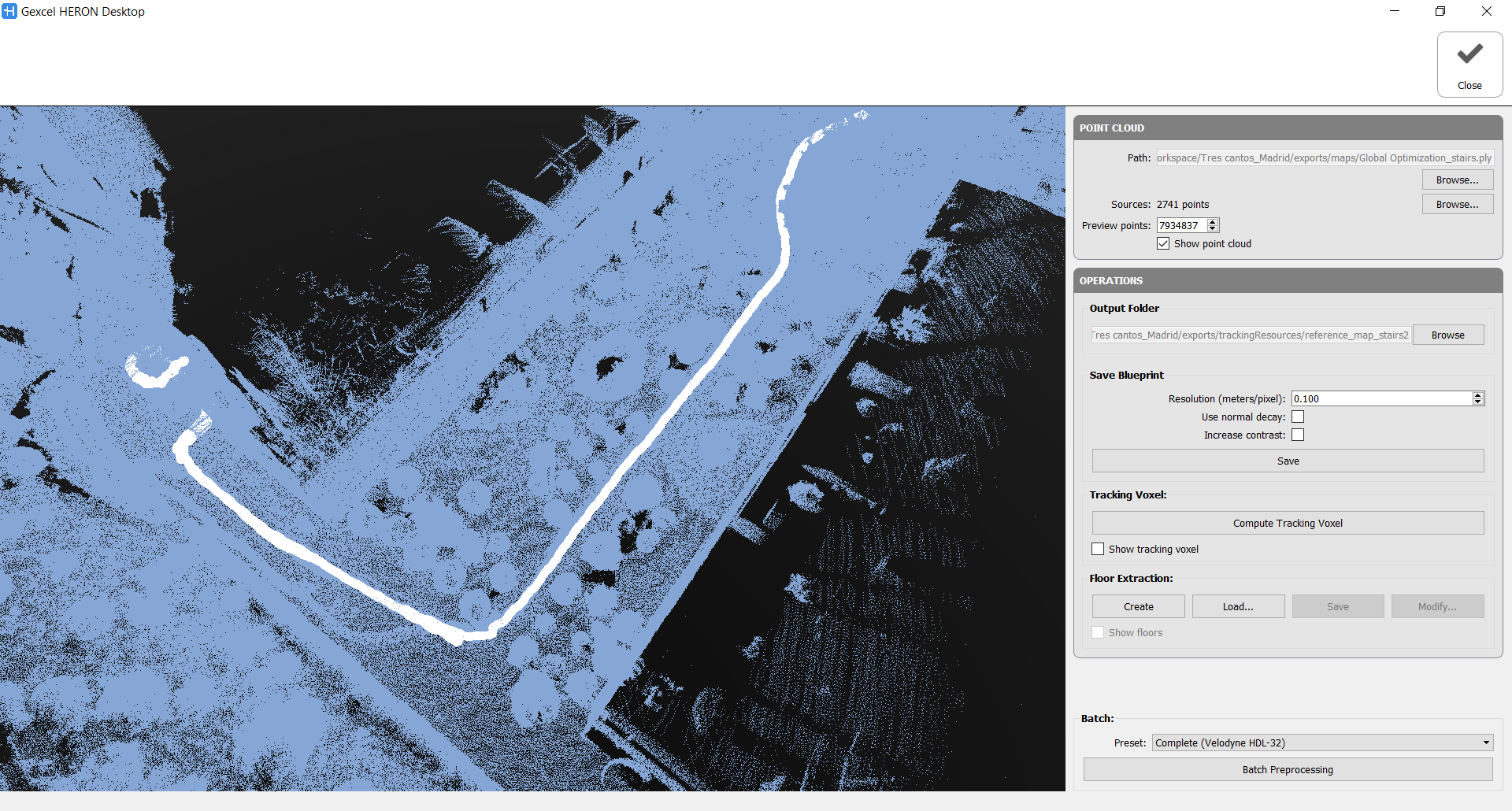
Point Cloud
Select the path in which the point cloud used to create the Reference map is stored.
The point cloud will be automatically loaded (blue point cloud) and subsampled. The white dots are indicating the position of the laser head along the trajectory, named sources. If a trajectory is not directly connected to these points, load the .txt file containing them.
Note that by using the Create Reference Map command in Reconstructor® the imported data is already correctly composed.
Operations
Output folder
Select the path of the Output folder in which you want to store the Reference map (the default folder is ....\exports\trackingResources) and the desired name of the reference map.
The menu grows according to the selected operation steps.
Save Blueprint
It is possible to save a blueprint of the reference map, by setting the resolution [m/px] and the properties of the extracted image.
![]() To perform the next training, it is necessary to compute or load the Floors and/or navigable voxels.
To perform the next training, it is necessary to compute or load the Floors and/or navigable voxels.
Let's analyze the Batch Processing
The step-by-step processing for the Reference Map creation is composed by four actions:
1. Tracking Voxel
In this step the point cloud is voxelized and analysed according to the set parameters, below explained. It is an approach independent from the other steps.
- Voxel size: defines the dimension of the voxel used to subdivide the 3D space.
This value could be decreased to 0.05 m for large environment challenges. - Normal calculation: given the input cloud, indicates how normals will be calculated.
Nearest: takes the already existing normal of the nearest point in the original cloud
Average: averages the normals in the original cloud of all points that fall inside the voxel
PCA: uses all the points that fall inside the voxel to compute a new normal by extracting the principal components of the distribution (plane fitting).
- Min neighbour voxel: how many full voxels have to be present in the local neighbourhood (28 contiguous voxels) for each voxel to be considered as valid.
- Min point per Voxel: how many points of the original cloud have to fall inside the voxel for it to be considered as valid.
The tracking voxel computation is lastly depending on the
- Maximum NN distance (in meters): This value refers to the tracking voxel creation. This voxel stores, for each empty voxel, a link to its nearest neighbour. Given the ‘Maximum NN distance’ parameter, an empty voxel will store the link to its nearest neighbour only if the second is closer than the provided value.
![]() By checking "Show tracking voxel" the computation time could increase a lot.
By checking "Show tracking voxel" the computation time could increase a lot.
At the end of the process a tracking.voxelGradient file is saved in ..\exports\trackingResources\FolderNameReferenceMap.
2. Floor Extraction
This step explores the 3D environment and extract the floors, analysing all the potential floors (considered as walkable surfaces). The relative parameters are explained below.
The cloud voxelization is analogous to the Tracking voxel one and the parameters are the same.
- Height & Radius [m]: define the bounding cylindrical volume exploring the environment. Used to detect if, standing over a potential floor cell, the user will hit other elements (i.e. furniture).
- Max. step distance [m]: expresses how much the user can move over the floor (XY plane) in a single step.
- Max. step height [m]: expresses how much the user can climb over the floor (Z axis) in a single step.
- Min. floor Z normal: minimum Z value of a voxel normal to be considered as a potential floor.
- Max. voxels in bounds: maximum number of full voxels inside the bounding volume of the user allowed.
The proposed floor can be changed by binary operations through the Modify button. They allow you to modify the shape of the floor by growing or shrinking the area occupied by the floor, working in all direction or only in XY direction. It is also possible to close the holes in the floor (e.g. due to the presence of furniture) and open (separate) the areas connected by a poor number of voxels.
At the end of the process a floor.voxel file is saved in ..\exports\trackingResources\FolderNameReferenceMap.
3. Navigable Space Extraction
This step detect all the navigable space above the floor in a range of heights where the laser head normally is.
The input parameters are the following:
Radius [m]: when evaluating if a voxel is navigable, the bounding volume of the user will be considered as a cylinder with the provided radius, going from the floor to the current voxel height.
Min & Max height [m]: range of heights above the floor where the sensor can be placed.
Max voxels in bounds: maximum number of full voxels inside the bounding volume to consider a navigable cell as reachable.
Also in this case the proposed navigable space can be changed by binary operations through the Modify button, following the same above criterion.
At the end of the process a navigable.voxel file is saved in ..\exports\trackingResources\FolderNameReferenceMap.
4. Kidnapped Training
It generates synthetic views of the point cloud in order to compute descriptors associated to a specific pose of the sensor. It requires to select the sensor that will be used (Velodyne model), the size of the offline rendering (FBO with/height), the view range of the sensor (near/far clip), how many random locations we want to generate per voxel cell of the navigable space (training density), the size of the descriptor to use (bins W/H), and the orientation ranges we want to use for generating the random poses (typically +-10 degrees for pitch and 360 yaw).
The minimum distance field is used to ignore all points in the synthetic image generated that are closer than the specified value.
This step is quite time consuming and it works on the CPU.
At the end of the process a places.train file is saved in ..\exports\trackingResources\FolderNameReferenceMap.
Batch Preprocessing
The Batch preprocessing automatically runs some of these processes, by setting the relative Presets:
- Complete: runs the entire pipeline (floors, navigable space, tracking voxel and kidnapped training)
- Kidnapped: runs only the part necessary for computing the training data (floors, navigable space and kidnapped training). In other words, no tracking voxel.
- No Kidnapped: runs the entire pipeline but not the training (floors, navigable space and tracking voxel)
Complete and Kidnapped presets are available both for Velodyne HDL-32 and Velodyne VLP-16 laser scanner.
Follow the step-by-step video tutorial to learn how create reference maps.