Cut&fill volumes
|
|
This procedure implements calculation of cut and fill volumes. Given two meshes representing the same object (e.g. the same terrain) at different instants in time, the cut volume is the volume that the objectlost between instant 1 and 2, the fill volume is the volume that the object gained between the two instants. |
The simplest way to use this procedure is to drag in the recipe window one mesh representing the surface at time 1, another mesh representing the surface at time 2, and click OK. Reconstructor will return the volume of surface 1 integrated on the Z=0 plane of the current UCS, the volume of surface 2 integrated in the same way, the cut volume (by how much the surface was excavated between time 1 and time 2), and the fill volume (by how much the surface was filled (has gained volume) between time 1 and time 2).
|
|
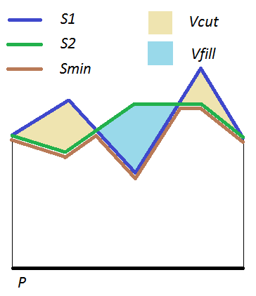
Given two surfaces S1 and S2, and a plane P, and assuming that the projections of S1 and S2 on P share a support C in common, a third surface Smin can be defined. Since each point in C, is the projection on P of (at least) one point of S1 and one of S2, the one of these points that is closest to P is defined as belonging to Smin. Let V1 be the integral of S1 on C, V2 the integral of S2 on C, andVmin the integral of Smin on C. Then the cut volume Vcut is given by V1 - Vmin, and the fill volume Vfill is V2 – Vmin. |
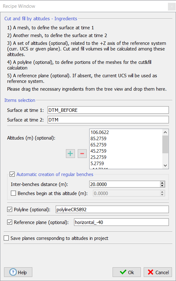
The user can specify several optional parameters, to satisfy special requirements. A set of altitudes can be optionally defined, Reconstructor will calculate the contributions to cut and fill volumes for each bench among two neighboring altitudes. The altitudes can be added and edited manually. Add an altitude by clicking the plus button, the minus button removes the selected altitude. Double-click on an altitude to change its value. Otherwise, the altitudes can be generated automatically by specifying a starting altitude and a fixed bench height. Check automatic creation of regular benches to do that.
These altitudes are by default referred to the Z axis of the current UCS. However, the user can change this, by dragging and dropping a plane that fills the field Reference plane (optional) and becomes the reference of all cut and fill calculation and of all altitudes.
The last optional parameter is a polyline that the user can specify to delimit the support C on which the surfaces are integrated. The closed polyline is projected on the horizontal plane Z=0 of the reference system and the support C in common between S1 and S2 is intersected with the area delimited by the projected polyline. Therefore, the volumes are calculated only inside the frustum defined by the polyline and the horizontal plane.
Once you have set all the parameters, press Ok and the computation starts, monitored by a progress bar and by messages in the log window.
See also Cut&Fill report.