User Coordinate System (UCS)
User coordinate systems are a central concept in Reconstructor®. In the same project, many coordinate systems can exist. An empty project contains at least a default UCS, called Main.
To create a new UCS, you can click on any project item and select Create UCS from this pose. The new UCS is added to the User Coordinate Systems group in the project window.
The current UCS
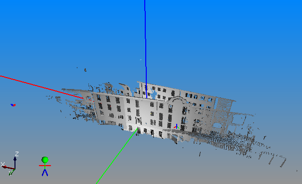
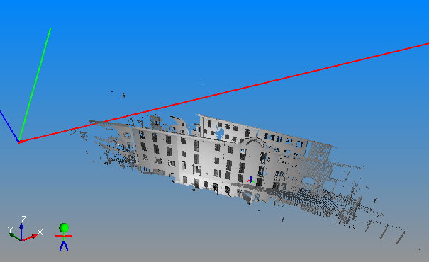
The Figures 1, 2 and 3 below show the same scene with three different UCS's set as current. The current UCS is visible from the long coordinate axes (the red is the X axis, green is the Y, blue is the Z axis).
|
|
|
|
|
Figure 1 |
Figure 2 |
Figure3 |
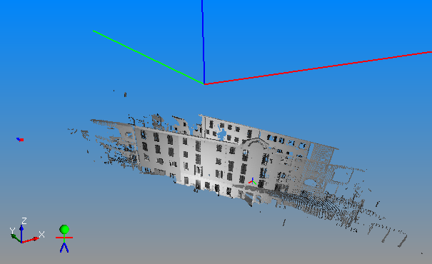
There is always one and only one current UCS. This is the UCS displayed in bold in the User Coordinate Systems group in the project window. To change the current UCS, right-click on another UCS and select set as current.
The current UCS is the current coordinate system for all the operations in Reconstructor®.
- Point coordinates in the Readout Window are displayed in the current UCS.
- Model position in the Adjust Pose window is displayed in the current UCS.
- Points in the Point List Window are displayed, imported and exported in the current UCS.
- All project data (point clouds, meshes, polylines, etc.) are imported interpreting their position in the current UCS, and exported saving their position as in the current UCS.
- The pose matrix shown in the Pose dialog is referred to the current UCS.
- The navigation system will perform “human” rotation movements assuming that the horizontal plane is the XY plane of the current UCS (see the option Enable human movements while rotating in Navigation Options for more information).
- Many Reconstructor® functions require a vertical direction and altitudes to be defined in your 3D scene. Cut and fill calculation is an example of these functions. The general assumption in Reconstructor® is that the current UCS's Z axis defines the vertical direction, and the altitudes are the distances of project items from the Z=0 plane of the current UCS.
- The Create/Edit Plane command allows to make a plane horizontal or vertical. Horizontal and Vertical directions, again, are always defined by the current UCS.
- Etc.
Therefore, if the user changes the current UCS, all the above-mentioned windows and functions will be affected in the way they visualize the coordinates or compute the models' positions.
UCS can be also created from the registration between two point lists.
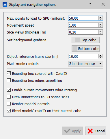
You can change UCS dimension, open Display and navigation options -> Object reference frame size [m] and insert the desired size.