Display and navigation Options
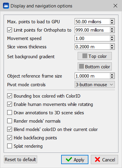
Max points to load to GPU (millions)
This option is used to set a maximum number of point to be rendered in the 3D scene. The limit is cumulative for all the loaded point clouds. It depends on the characteristics of the graphics card.
![]() Each loaded cloud is divided into 200,000 points buffers and, based on the user points budget, the number of buffers to be rendered is calculated.
Each loaded cloud is divided into 200,000 points buffers and, based on the user points budget, the number of buffers to be rendered is calculated.
It is always ensured that at least one buffer for each cloud is rendered. So it never happens that the user does not see clouds loaded, but, on the other hand, it is possible that the maximum budget set by the user (Max points to load to GPU) is exceeded.
Limit points for Orthophoto to ... (millions)
Check this option and set a value to limit the maximum number of points (belonging to the flagged and loaded point clouds) used snapping an orthophoto (or Virtual Scan). It depends on the characteristics of the graphics card. This limit is not concerning the X-ray orthophotos and Blueprints.
Movement speed
This option sets the translation speed when panning in pivot mode. It is an adaptive parameter, for the most part the default value (1) should be fine.
Slice views thickness
This option sets depth of a single slice when using the Slice view or the Horizontal section view.
Set background gradient
Change the uppermost and lowermost color of the background of the 3D rendering window.
Object reference frame size
All models and cameras can draw their local coordinate frame by enabling Draw coordinate frame property in the Property Window. Here the frame size (in meters) is specified to improve its visibility accordingly to the extent of the scene.
Pivot mode controls
Here you can select two options: “Reconstructor” and “3-button mouse”. These options are two sets of controls for the Pivot Mode. The second one is the default and is described here.
If you select “Reconstructor”, then in pivot mode the following controls apply:
- Rotate: To rotate the model around the pre-defined center of rotation (pivot), move the mouse within the 3D window while keeping the left button pressed.
- Pan: To pan the model in X and Y, move within the 3D window while keeping the left button and the Shift key pressed.
- Zoom: To translate the model along the Z-axis, move the mouse within the 3D window while keeping the left button and the [Ctrl] key pressed or use [Ctrl + mouse wheel] to zoom in and out along the Z-axis. In the latter case, if the mouse pointer hovers a valid 3D point, the zoom converges to that point.
- Change pivot: double-click the left mouse button plus [Ctrl+Shift ] on a valid 3D point.
Bounding box colored with colorID
When this option is checked, the bounding boxes of the project items are colored based on the item's colorID. If this option is unchecked, the bounding boxes are colored with the default (yellow) color.
Enable human movements while rotating
When this options is checked, a small human avatar appears in the bottom-left corner of the 3D rendering window. While you navigate in the 3D scene, you will experience that after doing many rotations, your viewing direction will still be oriented according to the vertical axis and to the horizontal plane defined by the current UCS. This is like a human being that, after rotating his head around his neck in many directions, when relaxing the head will go back into the natural position, which is in line with the spinal chord.
When this option is unchecked, while navigating the 3D scene you will experience that after some rotations the reference to the UCS's horizontal plane is lost, and that you are floating in the space like an astronaut floats among meteors, without gravity force.
Draw Annotations to 3D scene sides
Annotations will be arranged on the sides of the render window, at the exact insertion point.
Render models' normals
View vectors that describe the normals directions for point clouds and meshes, if they have been computed.
Blend models' Color ID on their current color
It blends the color layer (reflectance, confidence...) whit the Color ID. This two features are available in the Property Window.
Hide backfacing points
This setting hides the points that are oriented in the opposite direction to the current point of view. The orientation is calculated according to the point normal. The surfaces scanned from a point opposite to the current point of view will be hidden.
For example, if you scan a room, the ceiling seen from above (therefore from outside) is made transparent and you can see the inside of the room.
![]() The effect is equivalent to the Cull face of meshes, but applied to point clouds.
The effect is equivalent to the Cull face of meshes, but applied to point clouds.
![]() This setting has no effect if the clouds do not have the normals.
This setting has no effect if the clouds do not have the normals.
Splat rendering
This setting enables / disables the rendering of point clouds through circular elements (splats) with the aim of reconstructing the surface of the point clouds, covering the "holes" given by discrete sampling. Any circular element has a radius defined by Point Radius (or equal to 2 cm if Point Radius is not computed), is oriented as the point normal and has the same color of the point.
![]() The point cloud normals must be calculated for splat rendering to take effect. It is also possible to make the rendering more precise by calculating the radius of influence of each point using the Point Radius Extraction filter. The radius of the splat also depends on the percentage of points rendered.
The point cloud normals must be calculated for splat rendering to take effect. It is also possible to make the rendering more precise by calculating the radius of influence of each point using the Point Radius Extraction filter. The radius of the splat also depends on the percentage of points rendered.
Click on Reset to default button to reset to default parameters.
See also Light Settings options.