Import Heron data
|
|
To import the Heron® data as it is after being exported from Heron® Desktop. |
The transition from Heron® Desktop to Reconstructor® is guarantee by two main steps:
|
|
STEP 1 | in HERON® Desktop saves the acquired points according to user defined parameters and colorizes (only for Color systems) them. |
|
|
STEP 2 | in Reconstructor® applies dedicated filters to the point clouds, generates the Blueprints and organizes points and images (streaming and single-shots) to be navigable along the trajectory using the Blueprint Navigator. |

|
|
Different parameters configurations can be used in HERON® Desktop and Reconstructor® to run the import process according to the desired time/result ratio:
|
STEP 1 | in HERON® Desktop
The correct way to transfer the Heron® data from HERON® Desktop to Reconstructor® is to use the ![]() Go To Reconstructor command in the HERON® Desktop toolbar.
Go To Reconstructor command in the HERON® Desktop toolbar.
|
|
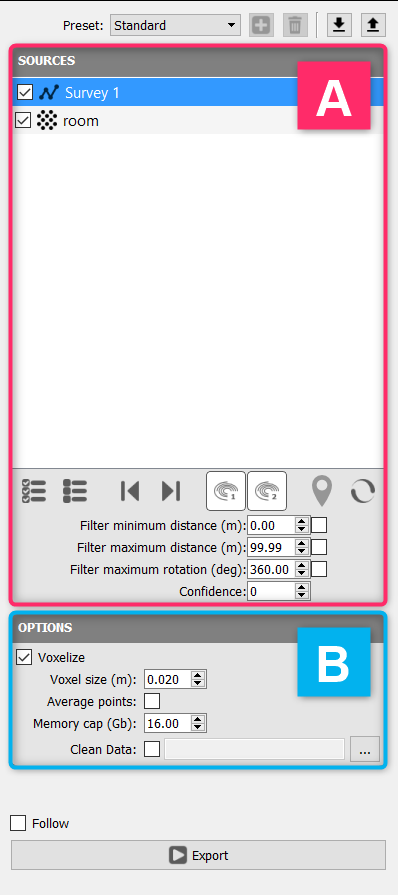
The GoTo Reconstructor dialog is subdivided in two sections: A - SOURCES The settings in this sections allow:
B - OPTIONS The settings in this sections allow:
|
STEP 2 | in Reconstructor®
Once the Go to Reconstructor process in finished, close HERON® Desktop Mapper and go back to the launch window, then press Reconstructor in the top toolbar.

A Reconstructor® project (linked with the current HERON® Desktop project) is automatically created.
|
|
In the HERON top toolbar menu of Reconstructor® press the Import Heron button to open a wizard window that guides you along the import phase. |
|
|
Import Global Optimization/Single Trajectory Click on this button to import the results of a Global Optimization as they are exported from HERON® Desktop and saved in the Heron workspace's folder exports/reconstructor. Select one Global Optimization from the proposed list and click on OK. |

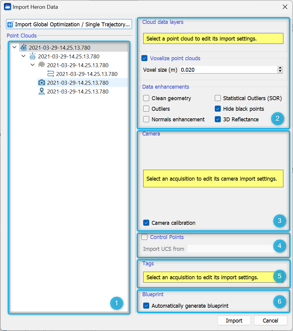
The wizard window is divided in 6 main sections:
- Point Clouds tree items
It gives the access to single items saved after the global optimization step in HERON® Desktop (point clouds, trajectory, images and tags). - Cloud data
After selecting a point cloud item, the color layers you want to keep, parameters and setting for importing, voxeling and filtering the 3D point clouds are selectable.
A Voxelization of the imported data can be applied, where the best aligned point is selected inside each voxel.
A Clean geometry filter can be applied to reduce the LiDAR noise without reducing the point cloud density.
Outliers filter is a noise removal filter that permits to delete the lonely points outside a detected surface.
The normals per each 3D point can be enhanced providing coherent inclination for each surface (important and useful when using fitting tools inside Reconstructor® or in third parties software - e.g. Edgewise®, Verity® to automatically detect geometrical features as walls, floors, ceilings -).
The Statistical outliers remover (SOR) filter removes outliers in order to obtain cleaner data.
The Hide black points filter hides all the points in the cloud that are colored in full black, i.e. RGB components [0 0 0].
3D Reflectance is a special color layer that mixes LiDAR intensity and point normals (inclination) to enhance both geometrical and surface characteristics. See more details about the point clouds processing at Cloud Processing and in particular at Pre-processing Point Clouds entries.
 - Camera
It includes the setting for importing images captured by Heron®. - Control Points
It defines the folder including the control points coordinates. - Tags
It includes the setting for importing tags. - Blueprint
It automatically generates a blueprint.
The tree structure including all the items saved in the Global Optimization is so displayed.
By clicking on a single item it is possible to edit its import settings (for details see Workflows - Parameters configurations).
By default the five sections from 2 to 6 are providing with a "medium" preset:
2. Assuming that in HERON® Desktop the survey is saved without any voxelization, Reconstructor® applies:
- a voxel size of 2 cm. The best aligned point is selected inside each voxel.
- a Black Points hiding
- the computation of 3D Reflectance, a special color layer that mixes LiDAR intensity and point normals (inclination) to enhance both geometrical and surface characteristics.
![]() These filters are applied only to Heron® data, not to any other cloud present in the Global Optimization.
These filters are applied only to Heron® data, not to any other cloud present in the Global Optimization.
3. The camera calibration is automatically applied on single-shot images to guarantee an optimal overlap to the 3D point clouds.
![]() It is really recommended to keep flagged the Camera calibration process.
It is really recommended to keep flagged the Camera calibration process.
4. Flag "Control Points" and choose, between proposed options, the folder including the Control Points saved in the linked HERON® Desktop project.
Every imported Global Optimization will have its own User Coordinate System.
![]() If working with pole tags, each list points to its own UCS and if working with manual tags only one default UCS is necessary.
If working with pole tags, each list points to its own UCS and if working with manual tags only one default UCS is necessary.
5. Tags acquired on the field are imported by default.
6. A blueprint of the surveyed clouds is automatically created and linked to trajectory, points and images.
Advanced parameters
To access the advanced parameters, select the specific items from tree structure [Section 1].
|
|
Global Optimization Includes all the objects in the Global Optimization you want to import. |
|
|
Single Tracklet It is related to the a single tracklet, composed by a point cloud, a trajectory, cameras (if present) and tags. |
|
|
Point Clouds The point clouds in the Global Optimization can be both |
|
|
Trajectory connected to the relative point cloud If the point cloud is the Heron® mobile data, a trajectory is directly connected to it. |
|
|
Cameras If present, the camera images are connected to the trajectory (both single-shot and streaming images, split in 2 different headings).
The folder containing the cameras and their calibration in the HERON® Desktop project is automatically linked, as well as the camera properties are automatically recognized. This is valid both for single-shot (Highest Resolution Images) and streaming images data set. The position of the pictures is automatically recognized. The cameras will be visible in the Blueprint Navigator. By selecting the camera items, the advance parameters for images import are reported. First of all the camera model and the directory containing the pictures. Then the calibration file position and the camera time offset to correctly set the calibration of cameras on LiDAr data. Flag the camera calibration to make the calibration effective during the data import phase.
|
|
|
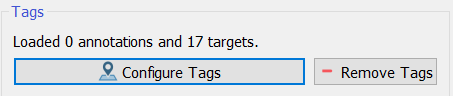
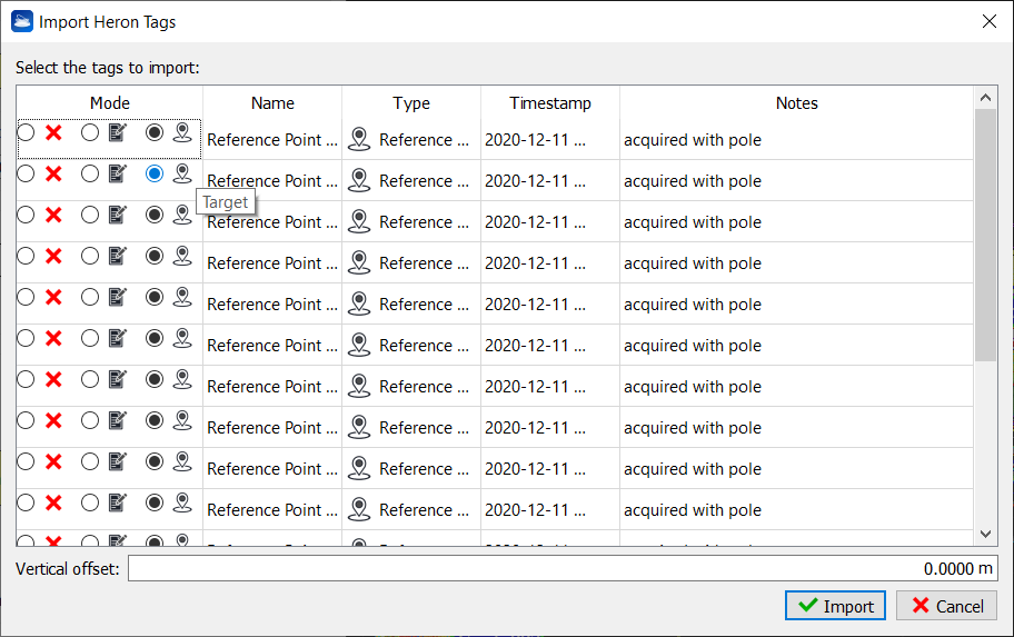
Tags Both annotations and targets are here included. By selecting the Tags item, the following advance option appears
By pressing the Configure Tags button a list of all the tags is showed and here you can choose to maintain or change the role of each tag inside Reconstructor®.
Check Check Check |


Blueprint
By checking Automatically generate blueprint a blueprint related to the point cloud(s) you are importing is automatically created. Its resolution is depending on the dimensions of the point clouds bounding boxes.
![]() This automatic blueprint is generated on a plane parallel to the XY plane of the current UCS (at the time of the import process).
This automatic blueprint is generated on a plane parallel to the XY plane of the current UCS (at the time of the import process).
To manage the blueprint layers see Create/Edit Heron Survey.
At the end of the process, a Heron® Survey including all the imported items will be inserted in the current project.
Note
If no Heron® Desktop project is already connected to the Reconstructor® project, by clicking on the Import Heron button the ws_info.json file included in the desired Heron® Desktop project's folder is requested. After this point there is the same process.