Project Items
Reconstructor®'s 3D world can be populated with several kinds of items. Items are listed in a tree view in the project window.
Models
The supported model structures are:
- Unstructured Point Clouds: a group of points with no relationship with each other
- Grid Point Clouds: a group of points organized in a 2D grid, like an image
- Triangle Meshes: a list of meshes, where each mesh is a collection of triangles with adjacency information
Other project items
- Polylines: created by contour algorithms or cross sections (exportable in a .dxf file)
- Camera views: preferred view points saved by the user with a definable projection among orthographic, perspective, cylindrical and spherical
- Projectors: images registered in the scene that can be projected on the geometry to create a texture map
- Annotations: user comments attached to valid 3D points in the scene. Distance and angle quotations are considered as annotations
- Flythroughs: spline trajectories defined by the user in order to create animations and movies
- Planes: useful to calculate volumes and cross sections
- Projects: useful to merge in a single location all the items of a sub-project.
- User Coordinate Systems: the user can create different coordinate systems with special purposes.
- Geometric shapes: primitives (planes, cones, cylinders, spheres, circles) created by a robust fitting algorithms.
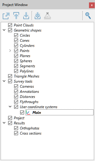
The Project Window
All the item groups are yet listed in this Project Window of a new clean project:
|
Load model: select a model (cloud of points or mesh) from the project window tree and press this button, the model will be loaded in PC RAM and if it is also checked |
|
Unload model: this button unloads from the RAM an from the main window the selected item(s). |
|
Export model as: depending on the type of object selected, an export window will appear; there are many formats available, see here. |
|
Search project item: searches through the items of the project. |


Contextual menu functions
The contextual menu contains, among other functions:
- Load/Unload model: each model can be loaded or unloaded to free main memory
- Save: this command is available only if the data or properties has been modified
- Save copy as: save a copy of the model or export to another file format. The following dialog allows to browse for the file location and format (Files of type combo box)
- Go to: center the 3D window to the bounding box of the model. The view point is computed so that to contain the whole bounding box in the viewport. Warning: this could place sometimes the model far away, with the effect that it seems not visible. Therefore increase the max depth in the Options.
- Center to local origin: the view point is aligned to local coordinate frame of the model, with X rightwards, Y upwards and Z going out of the screen.
- Align to bounding box: the view point is aligned to the desired face of the bounding box of the model
- Pose: open the pose dialog to view and modify the transformation matrix and geo-referentiation of the model
- {Model specific operations}: list of specific processing functions.
See also project window dedicated chapter.