Topographic meshing
This function implements topographic meshing of a set of point clouds. This procedure takes a set of point clouds and creates a DTM regularly sampling the clouds. The resulting mesh is watertight if the default parameters are used, and it is colored according to the altitudes: points at minimum height are in red and points at maximum height are in violet, passing through all hues.
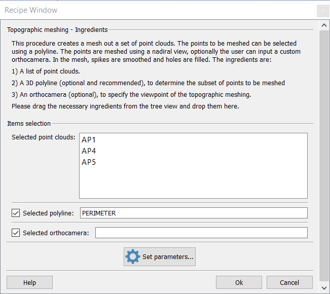
The user can also input a polyline to determine the points to be meshed (seen from a nadiral view or from a user-specified orthocamera). It is strongly recommended to input a polyline in order to help Reconstructor to concentrate only on the useful points and to speed up the process.
If the user doesn't specify any orthocamera, one is created so that it is nadiral (oriented towards -Z axis in the current UCS) and it contains the polyline. Once the user inputs the clouds and – optionally – the polyline, meshing starts by pressing Ok.
The procedure is composed of the following stages:
- Virtual scan is performed from the (nadiral) orthocamera, to uniformly sample the point clouds.
- Then, spikes in the resulting samples are smoothed using a median filter based either on a neighborhood of given size, or on a window of fixed size.
- Successively, a polynomial interpolation (ordinary gridding) is used to fill holes. This eliminates holes in the samples and guarantees the result mesh to be watertight.
- Then, a part of the obtained grid point cloud is selected using the polyline and the orthocamera. The selection with polyline allows the user to specify the region that he/she wants to be meshed.
- Subsequently, a median is applied to the resulting grid, to smooth it out.
- Finally, the resulting mesh is obtained by multiresolution meshing, filling all holes.
The mesh is saved in the project, under the name Topographic mesh of <n> clouds.
This procedure is relatively fast and useful especially for terrains. It outputs a mesh with nice properties: watertight, light and smooth (without spikes). The procedure can be customized by clicking the set parameters button.
Topographic meshing parameters
In this dialog you can set the parameters of the topographic meshing procedure.
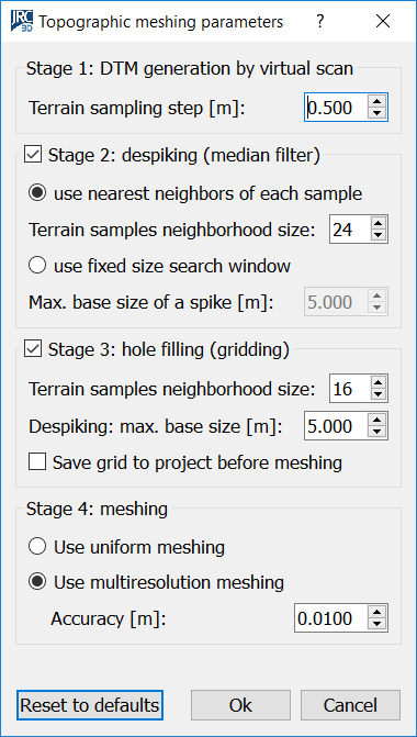
This dialog shows from top to bottom the four stages of the topographic meshing procedure. You can customize the parameters of each stage, and even decide to skip stages 2 and 3 by unchecking the respective boxes.
- Stage 1: DTM generation. The terrain sampling step is the fundamental parameter of this procedure. It is important to pay attention that this step is meaningful in relation to the dimensions of the desired model. If I want a mesh of a terrain of 20 m², I shouldn't use a sampling step of 0,5 m, otherwise I'll get too few samples. A small step will produce more accurate and heavier meshes. A big step will give less accuracy and also less memory occupied by the final mesh.
- Stage 2: despiking. Despiking is very useful to delete noisy data (e.g. vegetation) and therefore to have more precise calculations of volumes and isolines on the resulting mesh. Despiking is done with a median filter running on the grid point cloud obtained in the former step. As the dialog shows, the median filter can run on the N nearest neighbors of a sample, or on a window of samples of fixed size, regardless of how many samples are actually in the window.
- Stage 3: hole filling. This is performed by taking, for each missing sample in the grid point cloud, the <neighborhood size> samples closest. Polynomial interpolation is used to decide the height position of the missing sample. After the hole filling, another median filter is run on a square of samples of fixed size. The user can save the grid point cloud obtained till here by checking Save grid to project before meshing. This can be useful for example to mesh the grid using a color not related to the altitudes.
- Stage 4: meshing. In the end, the grid point cloud is meshed using one of the two techniques described here. Since at this stage the grid point cloud should be smooth, regular and without holes, there is no reason to change these parameters except for very particular cases.
Use the Reset to defaults button on bottom left if you are not sure of what is happening. However, topographic meshing is so fast that it is worth to try many combinations of parameters and compare the results.
See also other Meshing techniques.