Create Maps
|
|
This process creates a set of maps by splitting the full trajectory into a set of Local Maps. They are used, subsequently, to align the model. |
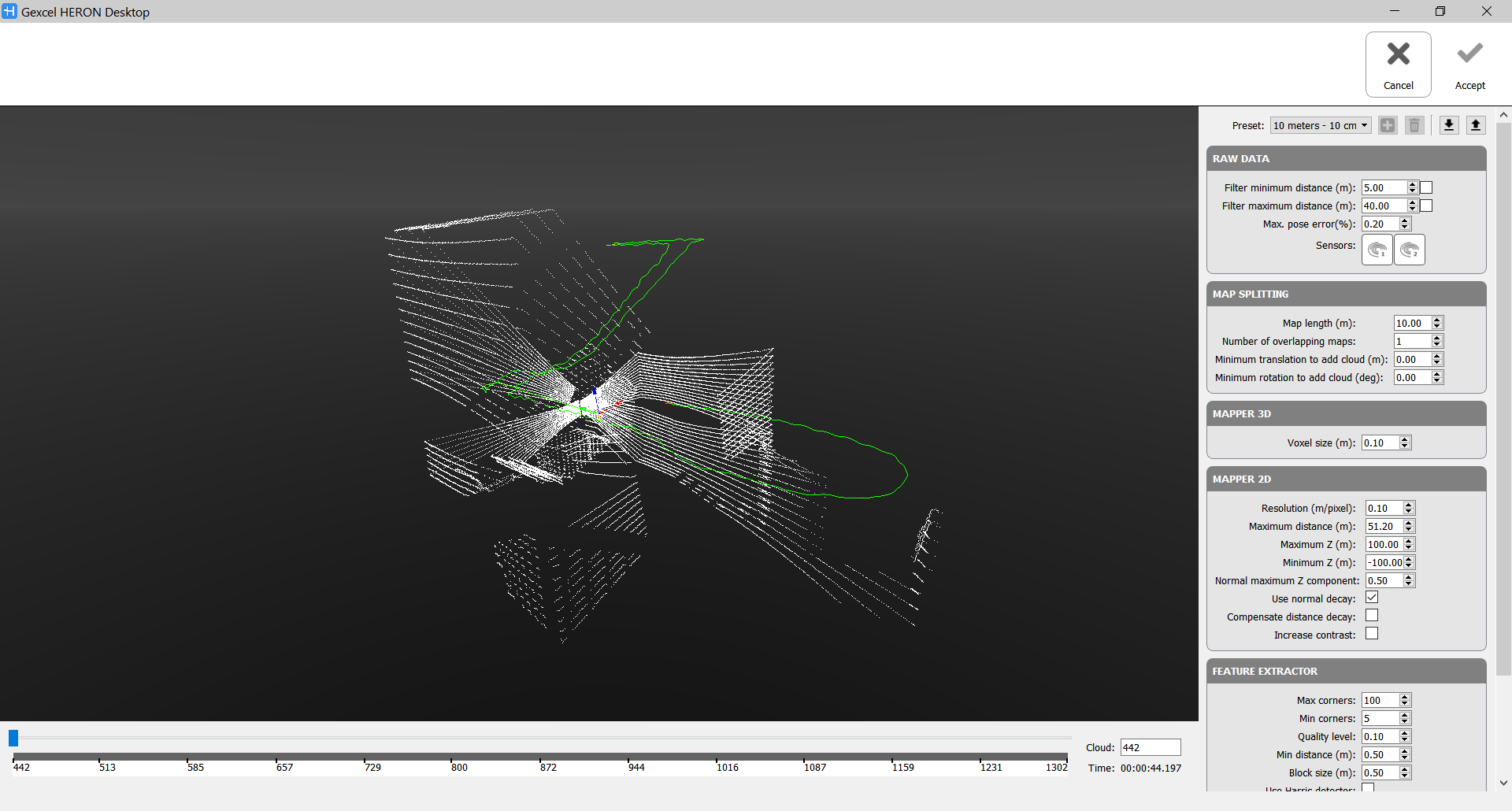
Select the tracklet in the project and click the Create Maps button.
If you are in the Expert Mode, at the right side of the screen the parameters are listed, otherwise you can see only the presets. Two preset classes are initially available: 10_meters and 25_meters, depending on how the system is being used. 10m is a good length for short acquisitions. 25m is faster for longer ones (and also for car modality). For each class a subdivision referred to a different resolution is applied.
By changing the preset, the parameters hereafter explained are automatically re-defined, but you can manually change the parameters as for your preference.
|
|
After setting the parameters (below explained) click the Run Mapper button to start process. |

|
|
At the end of the process, click the Accept button to apply the process just done |
|
|
or click the Cancel button to refuse the process just done |


![]() These maps are not the final model but they are used only to align the model. So, the parameters used to create them are not the same parameters used to export the final model.
These maps are not the final model but they are used only to align the model. So, the parameters used to create them are not the same parameters used to export the final model.
Raw Data
- Filter minimum distance [m]: Check ☑ and set a value X to not take in account, during Create Maps process, points at a range distance shorter than X meters.
Use this filter in case of moving people and/or objects like vegetation close to the sensor and objects useful to a good alignment far from the sensor. - Filter maximum distance [m]: Check ☑ and set a value Y to not take in account, during Create Maps process, points at a range distance longer than Y meters.
Use this filter in case of moving people and/or objects like vegetation far from the sensor and objects useful to a good alignment close to the sensor.
If no labels are checked all the acquired points will be considered during Create Maps process.
This filtering is independent of the analogous filtering in the Odometer phase, as well as the on in Export step.
- Max. pose error [%]
- Sensors
When managing data from the Heron MS Twin's system (composed by 2 LiDAR sensors), you can decide whether to export the data referring to both sensors or to one only, depending on the geometry of the environment you have acquired. Select (highlight) Use laser 1 to create maps including the horizontal LiDAR sensor data
 Select (highlight) Use laser 2 to create maps including the sloped LiDAR sensor data
Map splitting
- Map Length [m]: How much you have to walk along the trajectory to separate a map to the other.
Inside a map we are assuming that there is not a drift between the clouds. - Number of overlapping maps: it's necessary that two consecutive maps have common parts to connect them properly.
Value 1 means that one map and the next one have 50% of overlap; Value 2 means that the second map starts at 33% of the first one and at 66% the third one starts, so there is much more overlapped.
For example, by using the standard preset 10 meters, the Map Length is 10 m and the Number of overlapping maps is 1, that means:
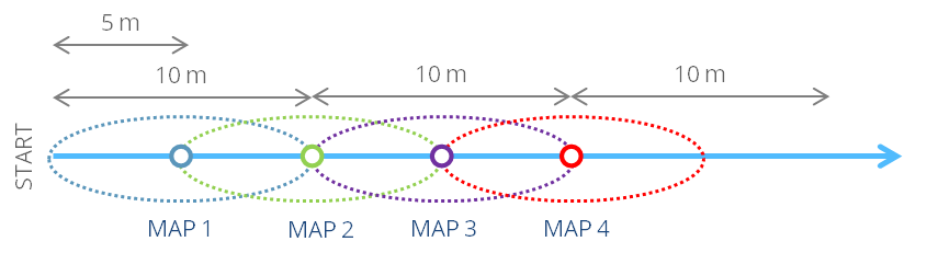
![]() 1 is the most reasonable value.
1 is the most reasonable value.
- Minimum translation to add cloud [m]: how much you have to translate (along the trajectory) to add a cloud to the map. A cloud is added to the map if the translation respect to the previous one (along the trajectory) is > value. Otherwise the cloud is skipped. If the value is set to 0, all the clouds are added. It's like a subsampling in walking distance.
- Minimum rotation to add cloud [deg]: how much you have to rotate (along the trajectory) to add a cloud to the map. A cloud is added to the map if the rotation respect to the previous one (along the trajectory) is > value. Otherwise the cloud is skipped.
Between the latter two constraints, the most restrictive will be applied.
Mapper 3D
- Voxel size [m]: dimension of the voxels used in voxelization. It defines the 'resolution' of the 3D Local Map generated during the process.
 Don't set a value higher than 10 cm. Don't too much increase the resolution if not necessary, to avoid creating large and heavy local maps and eventually add also noise. For indoor areas, for example, 5 cm is a good minimum value.
Mapper 2D
To extract features for the Global Optimization process, by projecting the 3D Local Maps along gravity direction, generating 2D images (blueprints), and doing a fast and efficient feature matching on the 2D space.
- Resolution [m/pixel]: resolution of the created blueprints (2D Images). It does not make sense to set a resolution lower than the voxel size.
- Maximum distance [m]: set the maximum radius of the projected area to keeping constrained the size of the 3D local maps.
- Maximum Z [m] and Minimum Z [m]: they define the maximum field of space taken in account for the projection.
- Normal maximum Z component: It tells the mapper (2D projection of 3D points along the gravity direction) which points are meaningful. Considering that points that are on the floor (normal Z component = 1) are useless, we only use points that are in vertical structures (normal Z component = 0) to create the 2D maps. By changing this value you tell the mapper how much you trust your gravity estimation. When the normal Z component is 0.5, the point is laying on a plane tilted 60 deg [arccos(0.5)]. This means that all points laying in planes between 60 and 120 degrees will be used. 0.5 is the most reasonable value.
- Use normal decay: If the checkbox is enabled ☑ points in vertical planes will weight 1, whilst points in 60/120 degrees planes will weight 0. Intermediate angles will be linearly interpolated. If the checkbox is not enabled all points laying in planes between 60 and 120 degrees will weight 1.
- Compensate distance decay: It tries to attenuate the point density decay of the scanner versus distance: as points are observed further, the spatial density of measurements decays quadratically. If this checkbox is enabled ☑ each point will be weighted with its squared distance to the Velodyne (the furthest the more weight). This is particularly useful when working with static scanners but, when it comes to the Velodyne, since the point cloud is so sparse, it makes no sense to compensate this distance decay.
- Increase contrast: Check ☑ to increase the intensities of the pixels once projected in the 2D images.
Feature Extractor
- Max corners: Maximum number of 2D features to extract from the projected 2D image. A high value gives more potential matches at the price of performance. A low value provides faster results, at the expense of missing some potential matches
- Min corners: Minimum number of 2D features to extract from the projected 2D image.
- Quality level: Parameter characterizing the minimal accepted quality of image corners. The parameter value is multiplied by the best corner quality measure, which is the minimal eigenvalue. The corners with the quality measure less than the product are rejected.
- Min distance (m): Minimum possible Euclidean distance between the returned corners. It indicates how close can be two features between themselves. It prevents having too many features around a single singular point.
- Block size (m): Size of an average block for computing a derivative covariation matrix over each pixel neighbourhood.
- Use Harris detector: Check ☑ to use a Harris detector.
k: Free parameter of the Harris detector. - Descriptor radius (m): Features are characterized using radial descriptors. The radius is the local size around the features used to compute the descriptor.
- Descriptor bin count: The descriptor stores the density of points around the feature split in angular regions (bins).
Follow the step-by-step video tutorial to learn how to run the Create Maps process.
|
|
It is possible that the far points are not accurate and, consequently, the created maps will not be correct. In this case, it is possible to select “Filter maximum distance (m)” and set the most appropriate distance. If the set distance is small (like 10/15 m), reduce “map length” to have a good overlap between the maps. |
|
|
It could be useful to split the original acquisition in independent parts (i.e. floors in a building) and optimize them individually using 10 meters. Then, once optimized, it's possible to generate very big local maps (40 meters) to connect them between themselves (i.e. using the stairs). Since floors do not connect between themselves, it makes no sense to look for new matches connecting them, so big maps accelerate the process. |