CAD Output
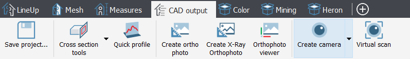
Cross sections, Quick profiles, Orthophotos and X-Ray Orthophotos can be created, edited, and used to take measurements in the 2D space.
All these outputs can be extracted from point clouds (both grid and unstructured) and meshes.
Points and polylines can be picked and created in the 3D space, but you can constraint them on a plane (to create a 2D entity) by using Drawing tools.
All these items can be exported into CAD software.
|
|
Cross Section Tools It contains commands and features to create cross sections and isolines of point clouds (grid or unstructured) and meshes, starting from cutting planes and other constraints: |
|
|
Creates vertical cross sections of models by simply picking two points in the 3D window you can access the relative command in the top toolbars. |


The following commands are used to create, manage and visualize precise, high-resolution elevations and plans (orthophotos) of your models:
|
|
Creates an Orthophoto and defines its position, size and field of view based on different parameters and methods. |
|
|
Creates an X-Ray Orthophoto from a set of selected point clouds. Main edges and borders are emphasized and displayed in the final Ortho view. |
|
|
Opens an orthophoto in the viewer to measure distances, angles and areas. From the viewer, the orthographic image can be exported in AutoCAD or published to the GoBlueprint viewer. |


The following tools are used to extract cameras and run virtual scans by using them.
|
|
Creates four types of camera (perspective, ortho, cylindrical and spherical). |
|
|
Creates a perspective camera placed in the current view point. |
|
|
Computes a Virtual Scan of the models in the 3D scene from a selected camera. The virtual scan can be saved as a 2D image, or as a grid point cloud, and exported to AutoCAD as a scaled Orthophoto. |
|
|
Exports selected point clouds and mesh models to be imported in 3DUserNet environment. |


